
Longitude Part I: The Geometry of a Sextant
The Purchase
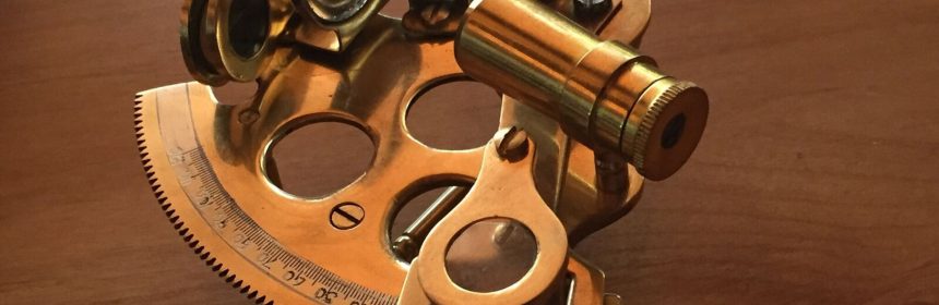
As I was only wanting to acquire a sextant for our book club discussion on Dava Sobel’s book “Longitude” (see below), I didn’t want to spend much money, and so put down $15 on Amazon for the brass sextant you see pictured above. I was hoping that the thing would be functional enough that I could demonstrate its usage, but found that not to be the case, as-is. I suspect that this object I bought was not so much a sextant, as a knock-off of a copy of a replica of a sculpture of an artist’s rendition of a sextant. I have now formed a vague notion that this item was produced in a back-alley of a run down area of Calcutta or Shanghai, by a person with little education but some skill in metalworking, casting, and possibly jewelry. Whether they have ever been on a boat, or could pick out the star Regulus on a clear night (city lights permitting), the question remains open.
One way or another, the good news is that after realizing this object was not functional, in the process of making it so I found that I learned a lot more about sextants that I ever would have, had I bought a truly functional precision instrument (for $200 more) in the first place.
So let’s get to work.
The Sextant
Though they look complicated, the simple idea behind a sextant (or quadrant, octant etc) is just to measure the angle between two things in the sky, either two bodies (like the moon and Regulus), or between one body (Polaris or the sun) and the horizon. This is easy to do on land, but at sea with everything moving it is difficult.
The clever idea (which it appears Newton had first) is to use two mirrors (actually, one and a half), in such a way that the two objects you are measuring can be brought “next” to each other optically by adjusting one of the mirrors. Once done, it is then just a matter of precisely measuring the angle the movable mirror was rotated. This nice diagram below (gleefully stolen from Wikipedia) shows how to get the (elevation) angle of the sun above the horizon:

Using the sextant and swing (From Wikipedia)
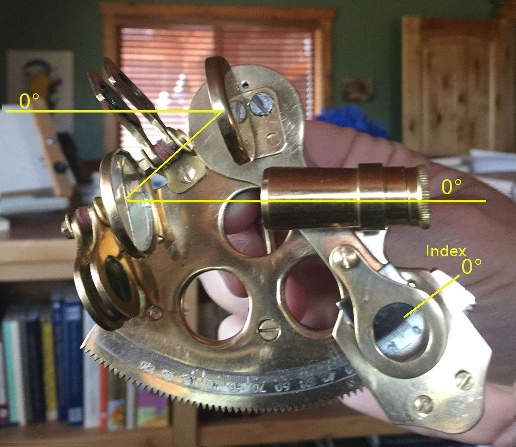
While we are on the topic, we should show the proper names of all the main components of the sextant:
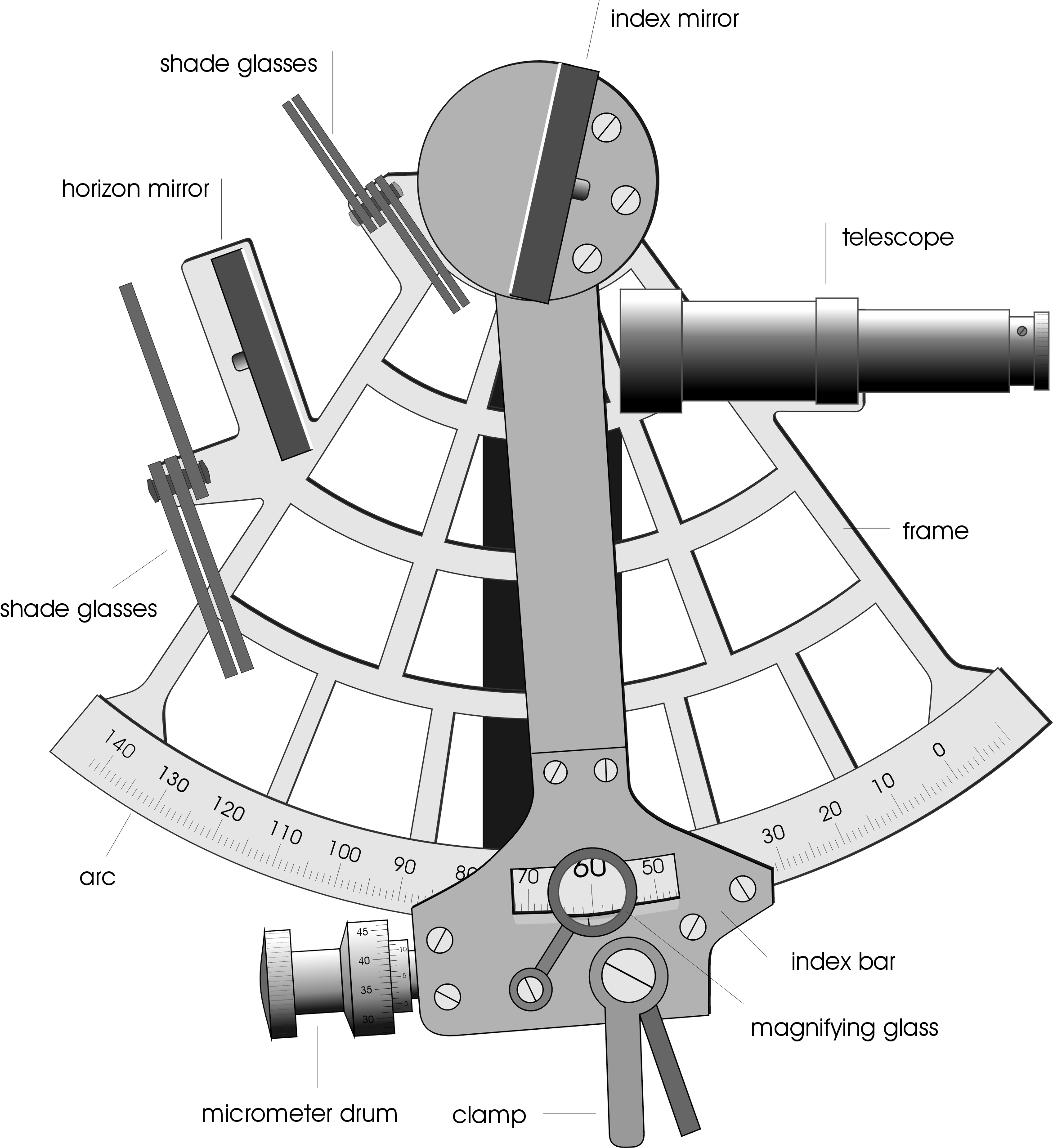
The main elements are the frame, which is the 60 degree wedge that forms the base of the sextant. There is usually a handle on the other side of the frame so you can hold it. Along the outside of the frame is the arc, which has degree markings, starting from zero on the right. The frame also holds the fixed “horizon mirror“, which is only half-mirror, half clear glass. The movable arm is the index bar, which has a pointer (the index) that points to the angle on the arc. The “index mirror” is fixed to the index arm, and is a full mirror that rotates on a pivot and brings the second object into view. The shade glasses are deployed for shooting the sun, and prevent you from going blind. The drum allows you to do fine adjustment of the index arm, which whose angle on the arc you can see with the magnifying glass. Finally, the telescope is a tiny low-powered telescope which allows you to get a good look at the objects whose angle you are measuring.
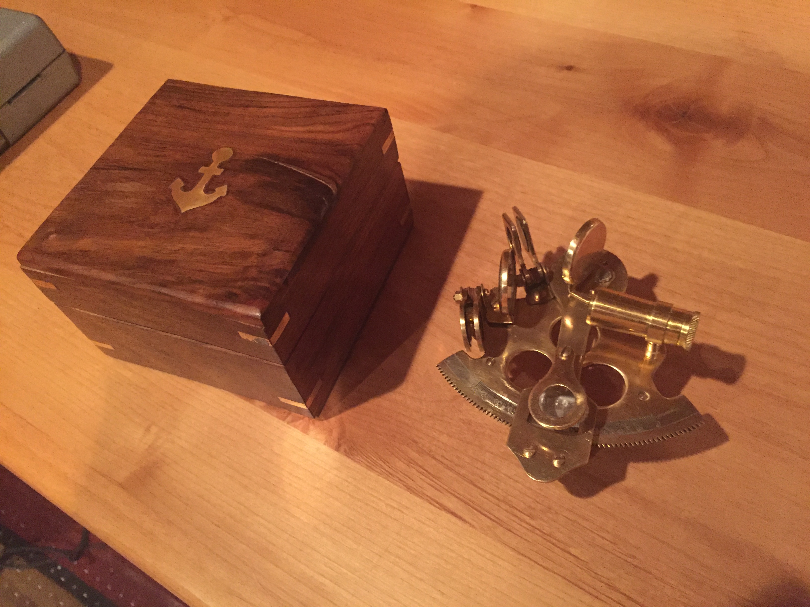
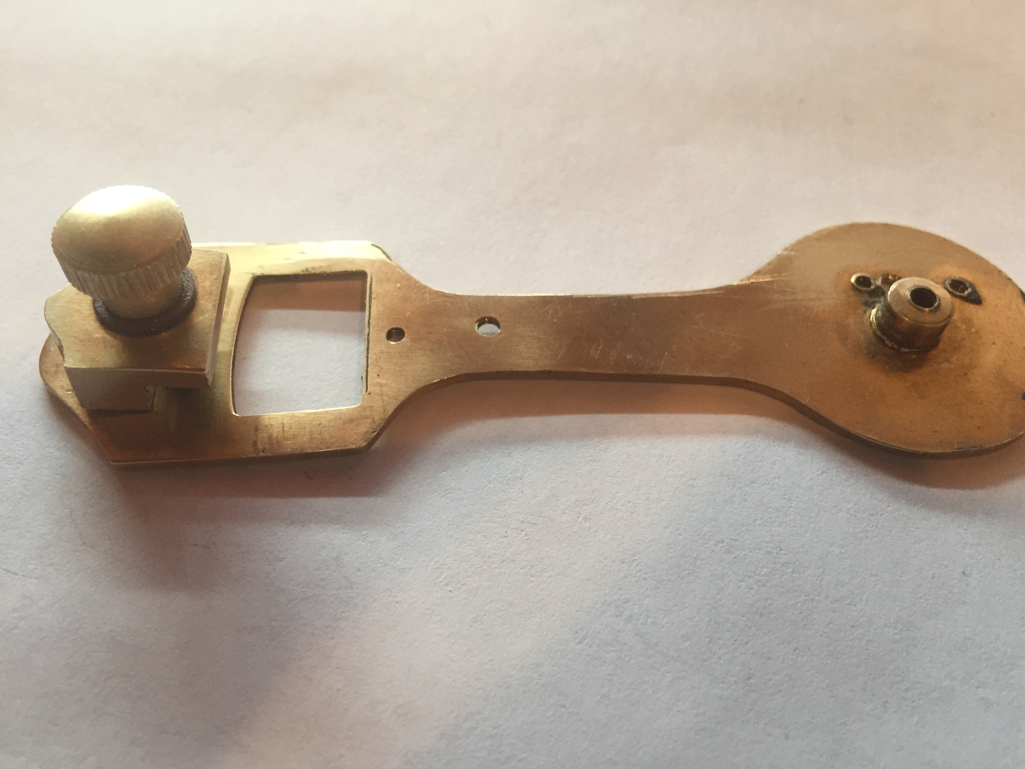
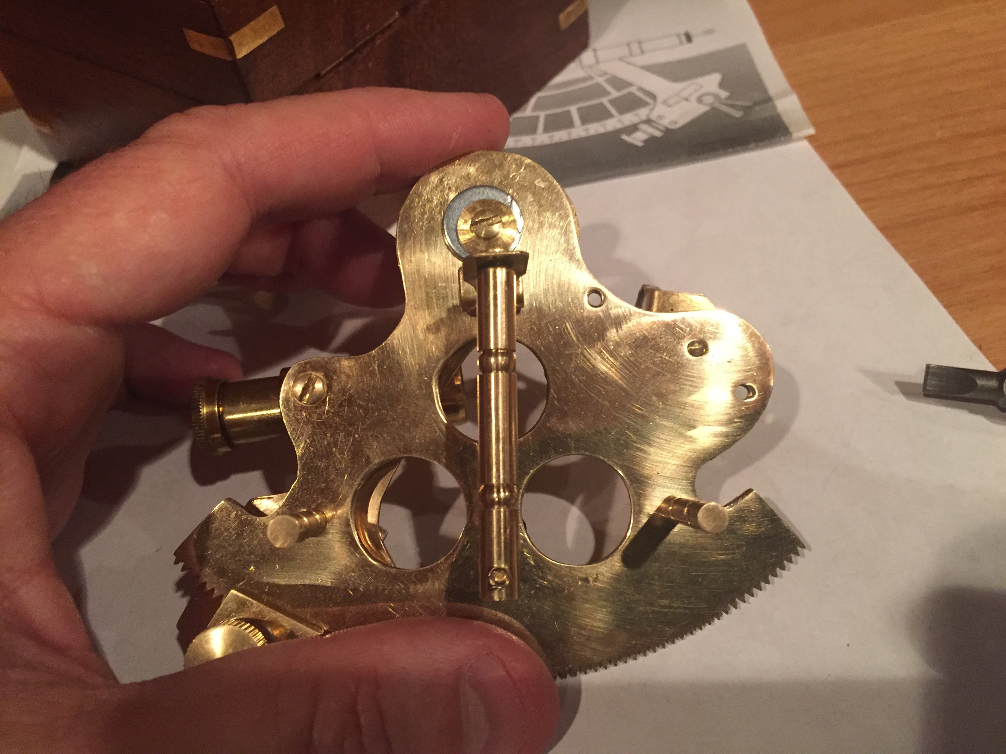
Here is an oblique view of my sextant, lying on its side. Ordinarily the geared arc is pointing down toward the earth. You can see that the horizon mirror is clear on the left side, and mirrored only on the right. So when you hold the sextant with the the telescope pointing to the horizon, the left side is looking straight ahead, at the horizon. Meanwhile, the right side is reflecting light from the index mirror, which is coming in at some angle above the horizon (indicated by the index arm).
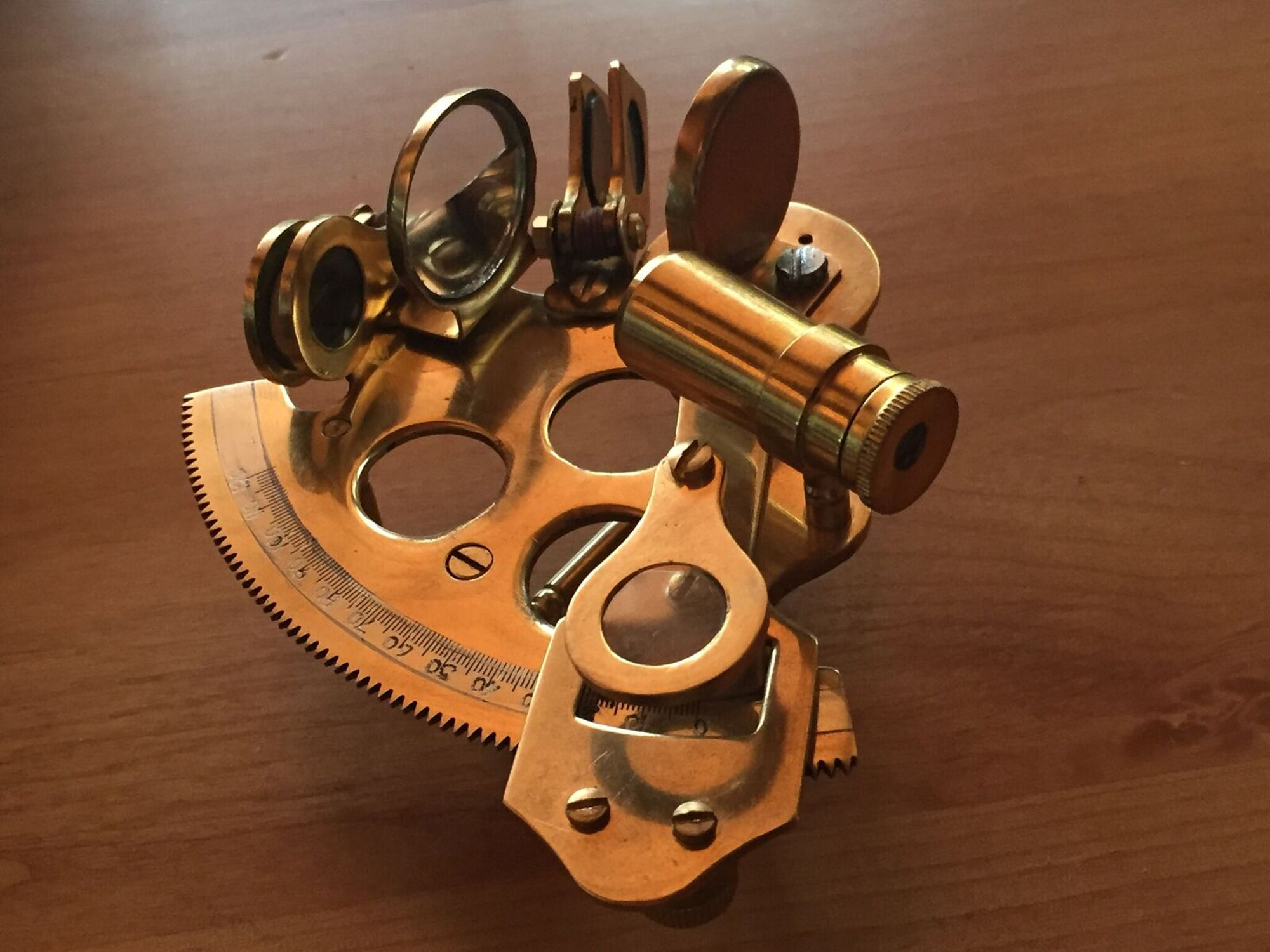
Here for example is the sextant with the index arm angle set to zero. This setting should allow the light from the horizon to bounce off the two mirrors and come into the little telescope at zero degrees. In other words, the view in both the left and right half of the horizon mirror should match.
The Geometry
The first geometrical question to address is, how does changing the angle θ of the index arm affect the angle β of the light coming in from the index mirror? Intuition suggests that since there are two mirrors, the angle will be doubled. Indeed, the rule is:
| The angles on the arc of the frame should be marked like a protractor, but with the angular values doubled. |
Of course (for me) this requires proof. We will need to draw a diagram:
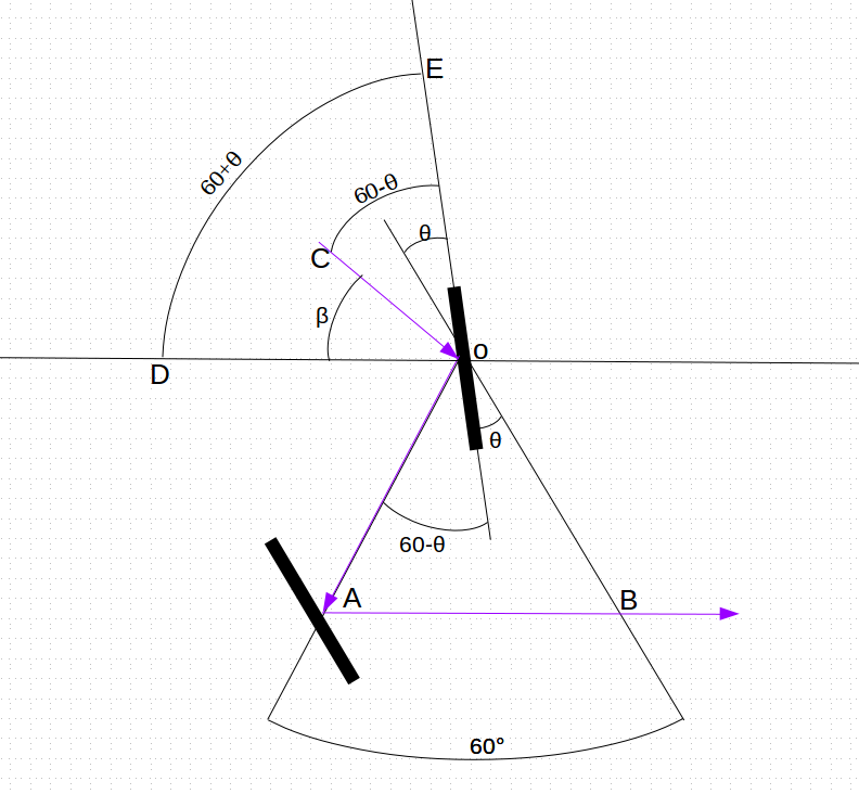
The lines in blue show the path of light coming in along line CO, reflecting off the index mirror at O, continuing along line OA, and then reflecting off the horizon mirror at A, finishing along AB to the telescope. Let’s assume the index mirror makes an angle of θ with the line OB, and so the angle between the ray of light OA with the mirror at O must be 60°-θ. Now light bounces off of mirrors at the same angle they came in, so the incoming ray of light CO must also form the angle COE which is equal to 60°-θ. Finally, the index mirror forms an angle EOD with the horizontal line OD of 60° + θ, meaning that the residual angle β we seek is the angle EOD minus EOC, that is,
β = EOD – EOC = (60° + θ) – (60° – θ) = 2θ
so β = 2θ. That is, the angles marked on the arc, in order to properly represent the incoming angle β of light on the index mirror, must be a value of exactly twice the actual angle formed by the index arm at that point from the zero mark.
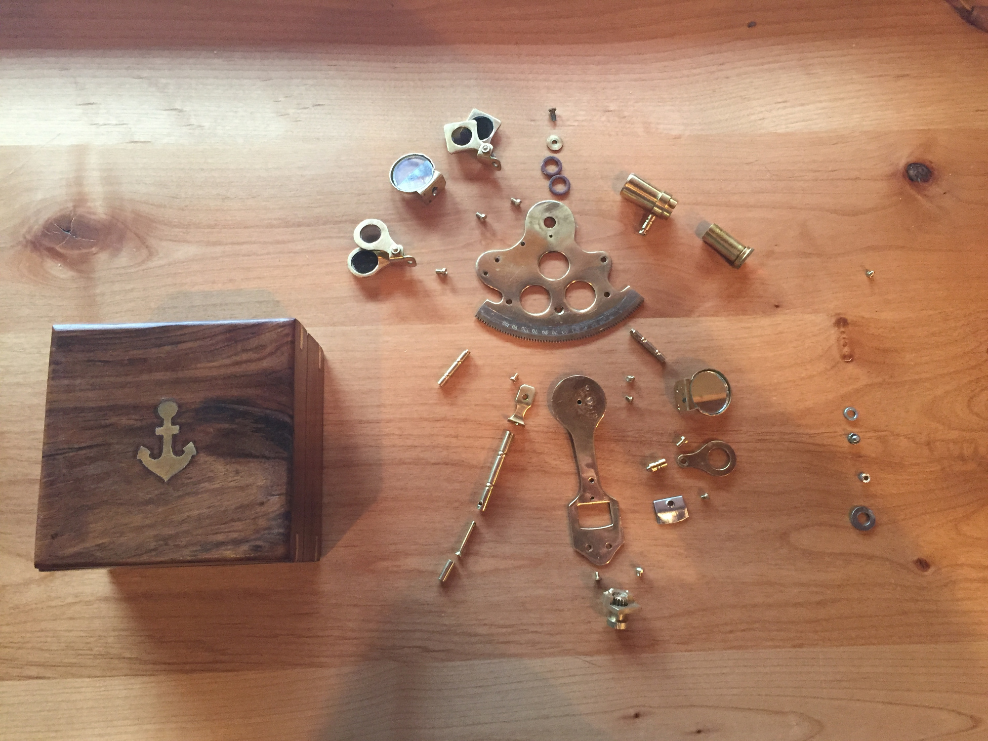
The Reformation
It didn’t take long for me to discover that my shiny new $15 sextant was not really functional as-is. It needed work. So the first thing I did of course (as is my nature) was to take the whole darn thing apart.
Issue #1: Frame
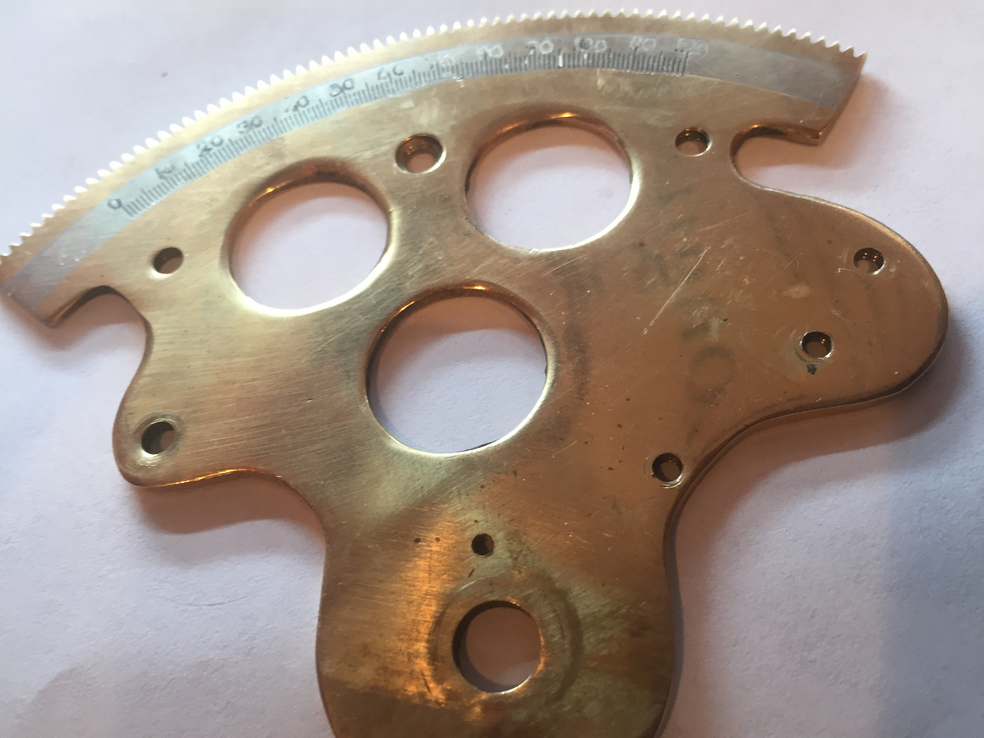 The largest and most important component is the Frame — the large flat bit with the round gear-teeth around the edge. This serves as the “optical bench” upon which all the components are mounted. In addition, the gearing must be uniform, and the markings on the Arc calibrated, so that precise angular measurements can be made.
The first problem was that the frame was not flat. As many of the components are mirrors which must be aligned in 3 dimensions, the subtle bends in the frame would throw off any measurement. With all the pieces now removed, I was able to flatten out the frame.
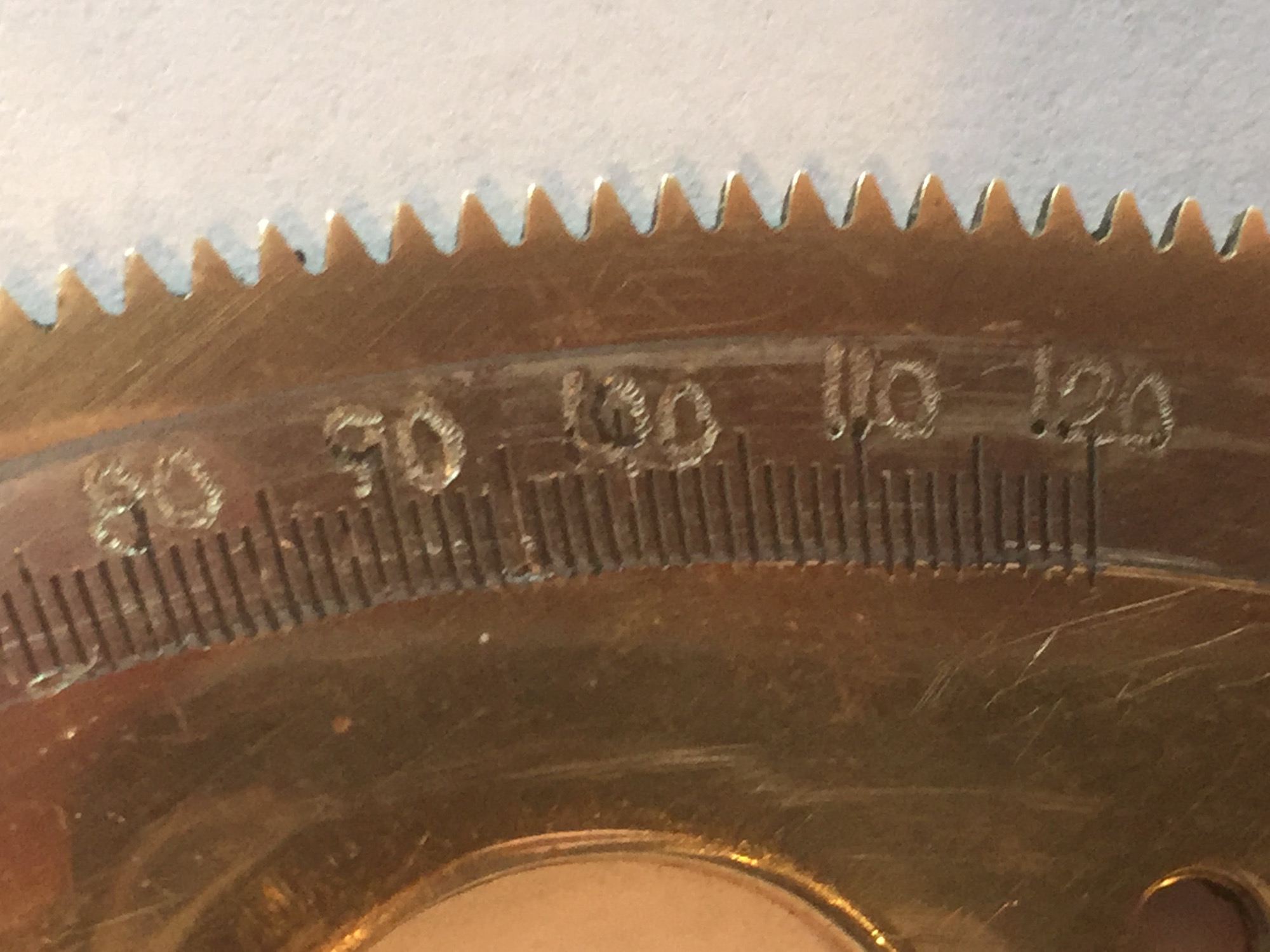
The second problem was that the markings on the arc were clearly not precise. One clue may be found in the numbers, which on close inspection seem to have been crudely carved in by hand with a Dremel or similar tool. This is not a problem that can be resolved, short of recasting the whole thing.
Issue #2: The Index Mirror
The first thing to note about the correctly made sextants in the previous section is that the index mirror is not aligned with the axis of the index arm, but slightly off, about 15 degrees. The one I got by comparison was not like that, and its mirror was lined up exactly with the index arm like this:
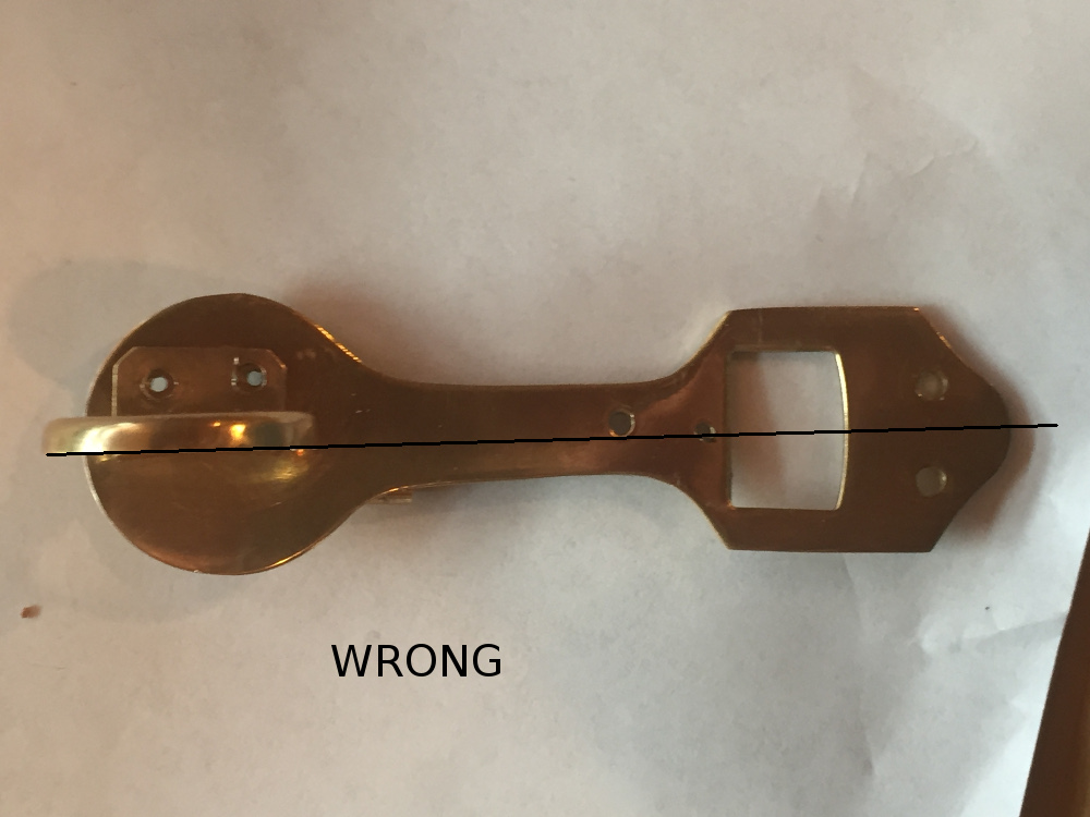 It turns out that this is wrong, or at least not very good or practical design. In fact, what it should look like is this:
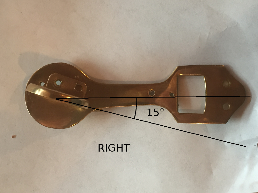
Now the actual angle does not need to be 15°, but should be around there. The rule here is a bit more heuristic and goes like this:
| The index mirror should not be in line with the index arm, but offset by an amount greater than zero but less than 30°. 15° is close to ideal. |
So what’s going on here? This is a mixture of mathematics and practical engineering.
Let’s parameterize this situation, and define a sextant whose index mirror is off-axis by an angle of δ a δ-Sextant. By this definition, what I bought is a 0°-Sextant, while the ones in the cartoon diagrams appear to be 15°-Sextants.
Okay, so what is so bad about my 0°-Sextant? Well, for looking at objects near the horizon (ie, where the index arm is near 0°), there is nothing really wrong at all and it works fine. I’m not familiar with the original design considerations, but two big factors have to do with the positioning of the horizon mirror, and the light-gathering ability of the index mirror. So let’s consider the horizon mirror first. Here is the geometry of the general δ-Sextant, with the index arm set at zero (so we are looking at the horizon):
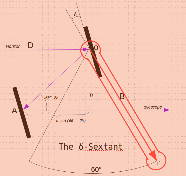 Now by the same argument as before, the successive reflections of the ray of light coming in from the horizon form an angle of 60° -2δ away from the horizontal. So in order to the light to drop down a height of h (so that it can reach the telescope), the horizon mirror must be set back by h*cot(60° -2δ) from the center of the sextant. As we increase δ from 0 to 30 the cotangent approaches infinity, making the mirror position increasingly impractical.
Therefore, taking a mid-point value of δ=15° would put the mirror in a practical location, much less than infinity. The mirror was mounted on the index arm with two small screws. I drilled two new holes for the screws and used a tap-and-die kit to thread the holes for the screws. The new mount for the mirror brought it close to the required 15 degree orientation.
Issue #3: Index Gear “Drum”
The index gear “drum” as depicted in the good diagram is a very precise worm-and-gear arrangement, with a “micrometer” fine-tuning for getting fractional degree measurements.
The knob is supposed to engage the gear teeth in the frame, and rotate the movable index arm (on which the index mirror is mounted). However, instead of using a worm-and-gear mechanism, it has a “direct drive”, in which the knob turns a wheel gear that meshes with the frame.
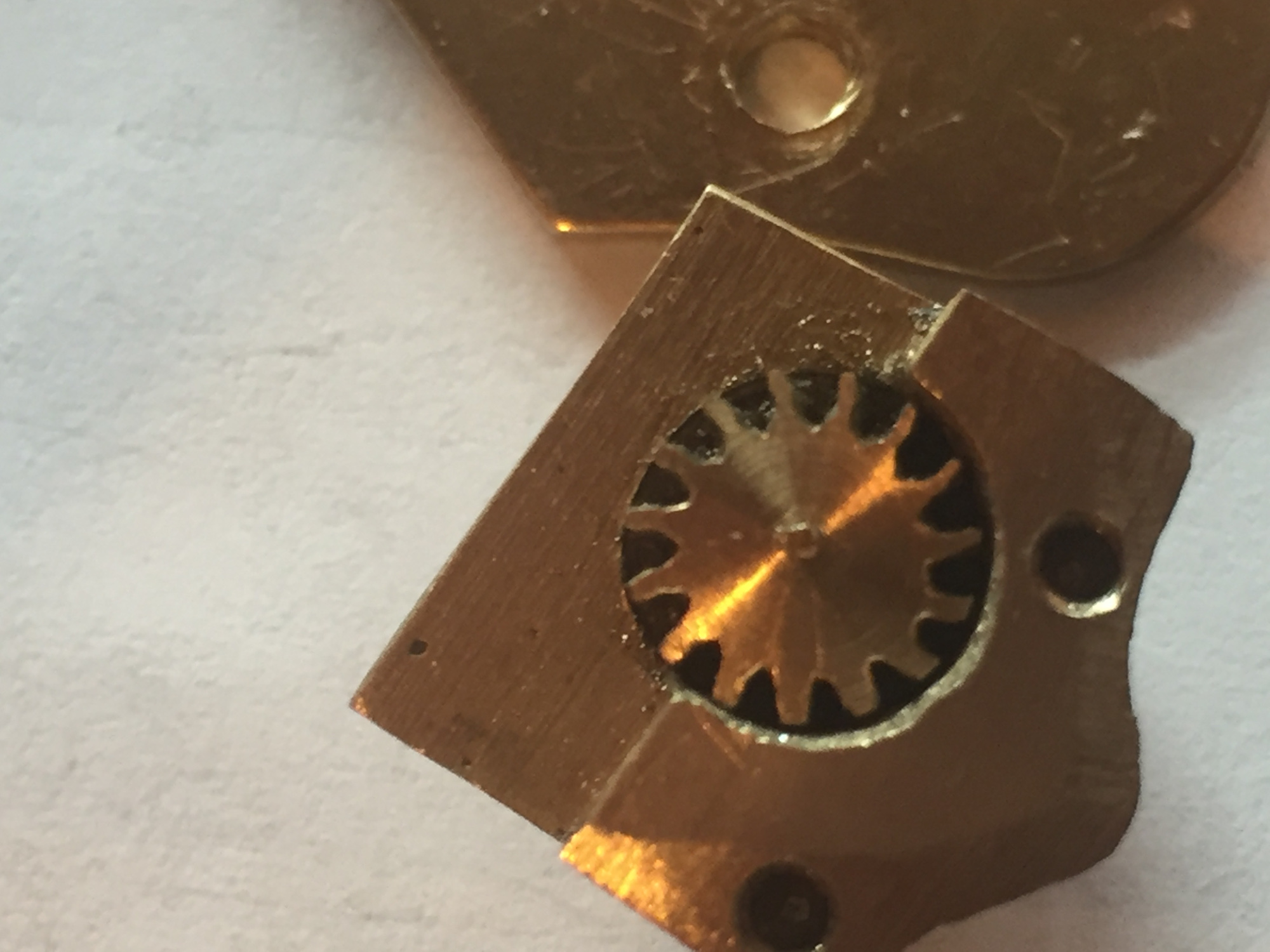
On close inspection, it was found that this gear must have been made by drilling out each of the gear teeth, and manually filing them down. The width and separation of the teeth have a visibly discernable variation, of about 5% or so. This bit is of the “juggling dog” variety, which is to say the amazing thing is not that it does its job well, but that it does it at all. Indeed, this gear tended to jam up at certain parts of the arc, and so required some additional filing just to get it to juggle at all.
Issue #4: Vernier Scale
In place of the high-precision worm-gear/micrometer, this sextant uses a “Vernier Scale“, which is admittedly a very clever device that was invented in ancient China (but named after French mathematician Pierre Vernier) to extract more precision out of otherwise crude devices. The general idea is to have a second scale that is just slightly smaller (9/10ths) than the base scale. This makes the smaller scale lines rarely line up with the base scale, except at one marking, which indicates how many tenths of a marking need to be added to the base reading:
Vernier Scale (wikipedia)
Here is what our vernier scale looks like (bolted to the index arm):
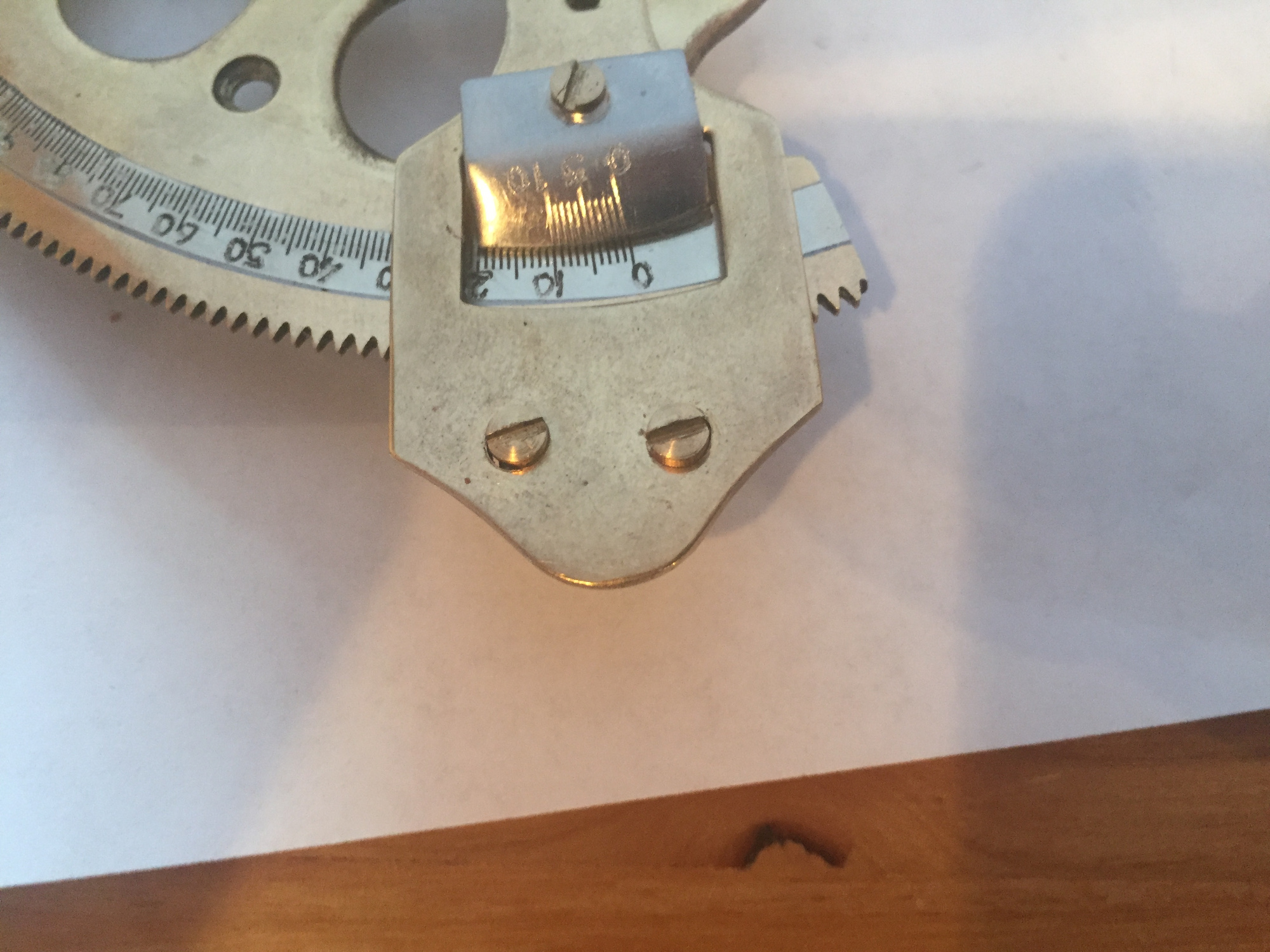
There is just one problem with our Vernier. The scale is not 9/10’s of the base, but 10/10ths:
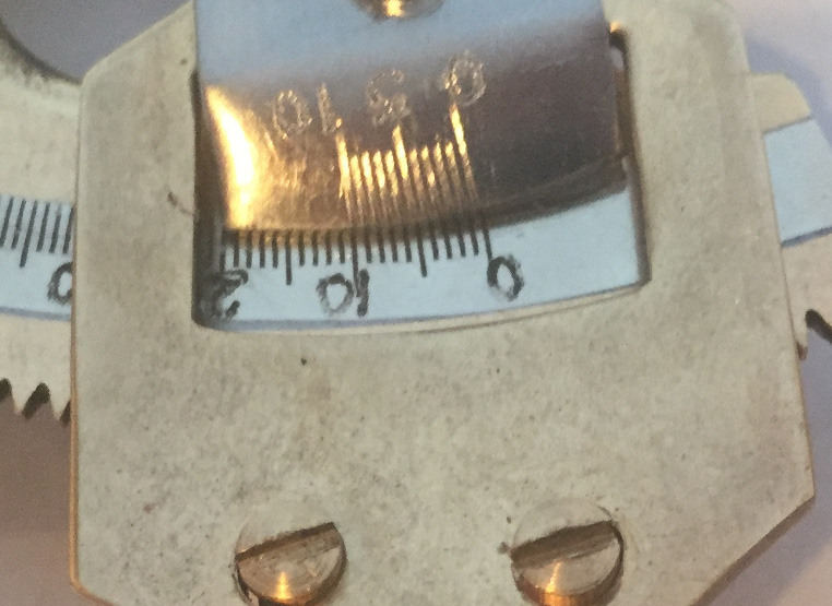 In other words, as a Vernier scale, it is totally useless. It is most likely that the poor starving artisan in Bangalore was just told to copy another copy and assumed the scales were supposed to match. There is no way to fix this. But as the gears that drive the index arm along the arc are themselves only accurate to about 5%, the additional precision that would be provided by the Vernier is pointless. At least it has a 0 degree line, with which I can line up the 0 on the arc and calibrate zero-degree separations.
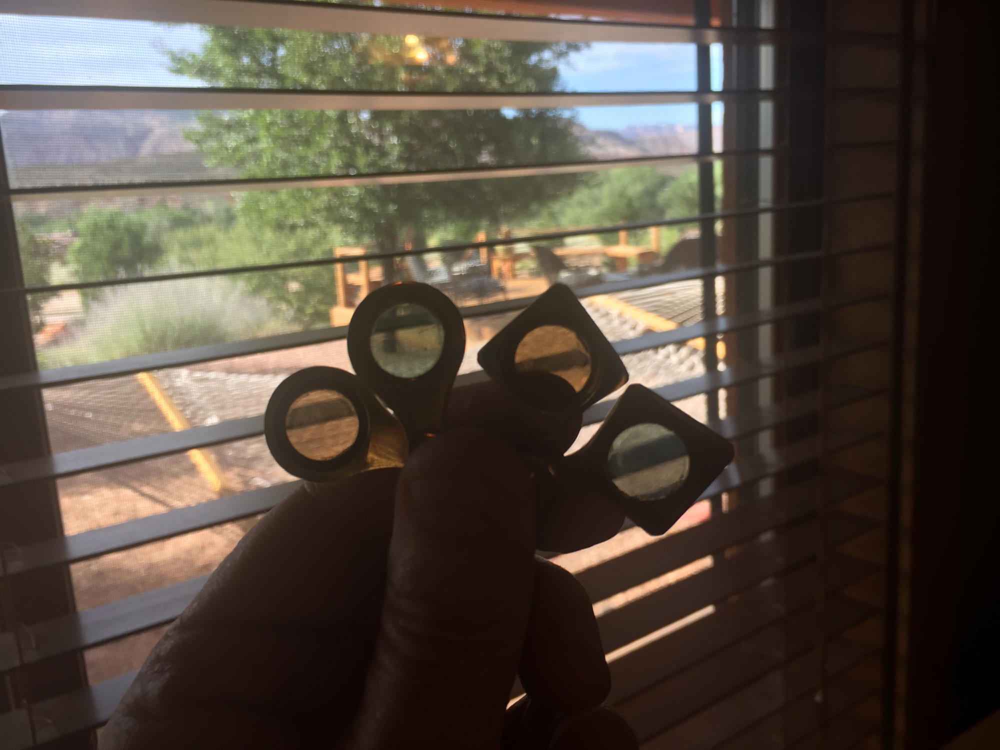
Issue #5: Sun Filters
While sextants are often used at night to measure distances between stars, they are also used to calculate the Sun’s altitude above the horizon (at noon for example). For this reason, sextants come with sun filters to prevent injury to the eye. The sun filters on this sextant are faintly colored glass, and should NEVER be used for any reason. Hopefully, nobody ever has used them. They are, like the rest of the sextant, purely decorative. The only fix is to replace with actual solar filters, or remove them altogether.
Issue #6: Telescope
To its credit, the telescope is not really a problem. It even appears to have a very slight magnification, and is properly aligned with the fixed horizon mirror.
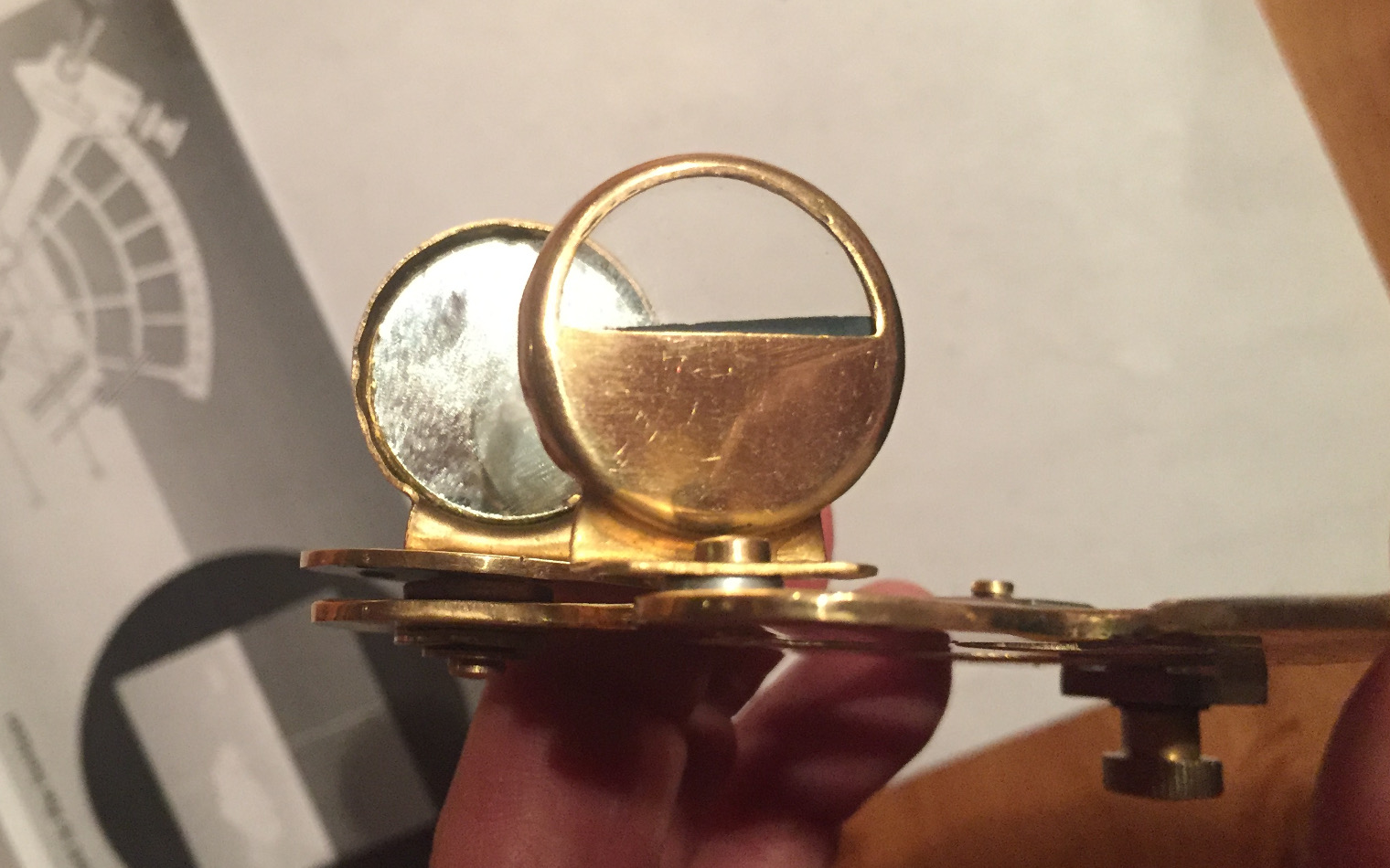
Issue #7: The horizon mirror
The horizon mirror, ideally, is split down the middle, with only the right half mirrored and the left half transparent, allowing the direct forward view to come through. Unfortunately, the mirror was glued in slightly at an angle, so that the vertical line between the mirrored and transparent sides is tilted by about 5 degrees. I did not want to risk breaking the mirror so left it alone. It was also offset vertically from the index mirror, and so added spacers to raise it up a bit.
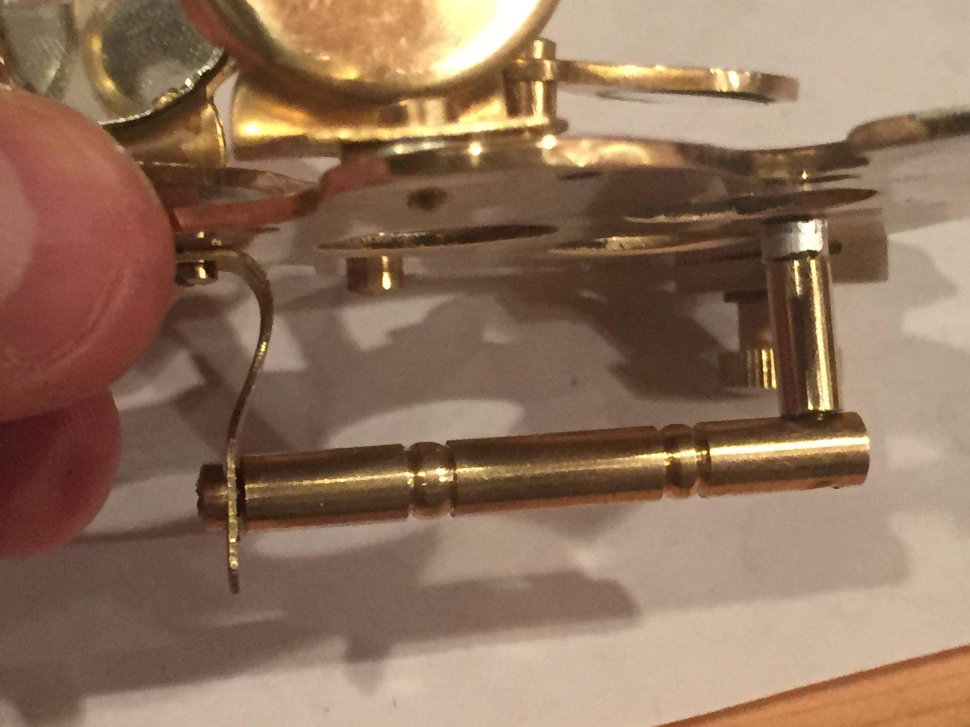
Issue #8: The Handle and Horizon bars
The back of the sextant has a vertically oriented handle, along with two posts which when aligned should match the horizon (when computing the sun’s altitude):
The vertical handle was not exactly vertical, and so I inserted a spacer to adjust the alignment:
Issue #9: Magnifying lens
The magnifying lens, intended to magnify the vernier and base scales for easy reading of the angle, doesn’t magnify. It appears to be an optically flat piece of glass, identical to the “sun filters”. I removed it as it only gets in the way.
Conclusion
This was a pretty but functionally useless toy when it arrived. After two weeks and a number of visits to Ace Hardware, it was almost serviceable enough to calculate separations to about 1 degree. I would not depend on it to save my life.